14 Apr 2010 08:04 pm
Posted by Dave under Mr. FixIt
Heated Motorbike Grips (Part 1)
The best thing since sliced bread.
 After years of procrastinating I finally (at Brenda’s prompting) purchased and installed heated grips on both of our motorcycles – last June! Then I continued the trend by procrastinating on posting this write up. As a reward for mentioning to Sean just how much more pleasant cool/cold weather riding is when you have warm hands, Sean has prompted me to describe how I did it. So here’s the skinny.
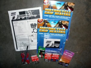
I decided to use Symtec Motorcycle Grip Heaters that are installed underneath the stock grips. In my research over a couple of years, I’d sort of settled on these as the simplest to install and the most cost effective grip heaters available. I ordered them in from the US when I couldn’t find a local supplier. Beyond grip heaters, I needed the following parts (acquired at Canadian Tire, The Source or Parts Source):
- 10A fuse and fuse holder
- Single Pole Normally Open automotive relay
- Terminal block for distribution
- 14G wire (I had 3 colours, for +ive, -ive & switching)
- In-line tap connector
- Assorted spade and ring lugs
- Heat shrink tubing in various sizes
- Assorted zip ties
- Electrical Tape
- Hairspray
- Multimeter
- Soldering iron and solder (soldering skills are optional)
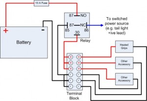
 Although you can certainly simply wire the grip heaters right to the battery and use the supplied switch to turn them off when not in use, it seemed far better to ensure that the grips could only draw power when the ignition was on. This prevents the inevitable forgetfulness from teaching you how to push start your bike. I broke the job into two parts; first wire up an accessory power distribution system, second install the grips. The basic plan was to create wire the grips up as shown in this diagram.
The first part of the job is to wire up everything in the diagram from the battery to the terminal block: fuse, relay, tap to switched source and the terminal block. The steps are:
- Park the bike securely in a well lit comfortable work area, use a center-stand or rear axle stand if possible.
- Prep the terminal block by adding required jumper wires to create a set of positive and a set of negative terminals.
- Remove the seat(s) to gain access to the battery.
- Figure out where you have room to mount the new components and how you will secure them. It’s all pretty light weight stuff, but you will want to zip tie things down so that they don’t flop around and ensure that they don’t interfere with the seat or other bits.
- Find a switched, positive lead. I used the license plate light lead as it is fairly easy to find and if you screw up and the license plate light stops working it’s not going to make the bike unrideable.
- Disconnect the battery (both terminals), you don’t want to work on the electrical when it’s hot.
- Wire things up in an organized fashion. I started with the ground side and worked around to the hot side. Use heatshrink where needed to protect from the possibility of electrical shorts.
- -ive from battery to terminal block -ive side
- -ive from terminal block -ive side to relay contact #86
- +ive from terminal block +ive side to relay contact #30
- +ive from relay contact #87(NO) to 10A fuse
- +ive from 10A fuse to battery
- Run a wire from relay contact #85 to the switched 12V source that was selected earlier (the wire for the license plate light, in my case) and hook into it with an in-line tap connector.
- Check all the connections, then re-connect to the battery using ring terminals under the battery post screws.
- Check that everything works, turn the ignition key on and listen for the solenoid to switch, then using a multimeter, check that the the -ive side of the terminal block is at ground and the +ive side is at +12V when the ignition is on. Turn the key off and listen for the solenoid to switch again and ensure that the +ive side of the terminal block is now unpowered.
If no smoke is observed and the bike doesn’t burn up, then that’s it for the first part. Total time for this was probably about 3 to 4 hours for both motorbikes, but that included an assortment of early season “while I’m in here anyway” tasks. The most time consuming bit was taking the tail fairings off to get access to the tail light wire. Here are some pictures of Brenda’s bike (blue SV650 curvy) and my bike (red SV650 pointy) that show how they turned out.
That’s about as much as I can manage for tonight, I’ll try to post part 2 of the story, how to install and wire up the grips, tomorrow.
Leave a Reply
You must be logged in to post a comment.


