24 Apr 2010 09:04 am
Posted by Dave under Mr. FixIt
Heated Motorbike Grips (Part 2)
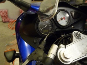 With a switched distribution block wired in as described in Part 1 of this write up, the heated grips can be added. This is a little more involved and requires a bit of patience to pull off the grips, run the wires, replace the grips,check for clearance, drill a hole (!) in the dash and make the hookup to the power distribution block. The good news is that since the power is already done and tested this step is mostly a mechanical exercise.
The process is pretty straight forward and the instructions that come with the Symtec grip heaters are pretty clear and easy to follow. The parts list was provided in Part 1, so here are the steps to get the grips all warm and toasty:
- Take the bar-end weights off the clip-on for both sides.
- Gently remove the stock grips from the clip-ons; start with the clutch side grip – it’s easier. The grip will be stuck on with an adhesive, fortunately nothing too tenacious, but it will take a little effort. Freeing the grip with out damage is not important if you are replacing the grips at the same time, just cut ’em off if that is the case for you. I was reusing the stock grips so I just carefully used a thin screwdriver and some compressed air to loosen the bond between grip and clip-on, then gently rolled/twisted the grip off. The throttle side is a little more difficult as the throttle tube is ribbed and that impedes progress a bit.
- Clean up the adhesive residue on each side with rubbing alcohol and a clean cloth. Clean the insides of each grip, too.
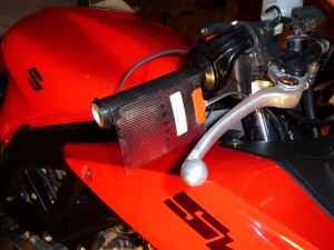 Test fit the placement of the clutch and throttle heating elements to see where you can run the wires and where the gap in the element will sit when attached. Again the throttle side is a little more effort as you have to carefully plan for the rotation of the throttle and how that will affect the routing of the element wiring. A bit of masking tape to hold things temporarily might help as you fiddle.
 When you have the element placement sorted, you can optionally wrap the clutch side clip-on with a layer or two of electrical tape before affixing the element. This will help to insulate the metal clip-on from the element and allow more of the heat to get to your hand. This picture shows the clutch-side element with two layers of black electrical tape underneath.
- Peel the backing on each element and affix them to the clip-ons. I added a single turn of electrical tape at the inboard and outboard edges of the elements to make sure that the grips don’t lift the element when they are re-installed.
- Zip tie the wires (not too tight, for now) to the clip-ons so that the grips can be reinstalled.
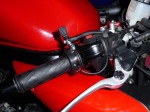 Reinstall the grips, clutch side first is easier and good practice. Spray some hairspray into the grip and, working quickly, slide the grip up into place. The hairspray acts as a lubricant to slide the grip into place and then, once it dries, acts as an adhesive to keep the grip firmly in place. The throttle side is, once again, trickier, you need to make sure that the grip sits properly on the throttle tube and does not bind or interfere with the smooth movement of the throttle.
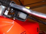
The throttle side picture shows the loop of wire between the grip and the first zip tie that allows the throttle to rotate with out binding. The wire loop needs to clear any part of the throttle cable mechanism that might interfere. The picture of the clutch side shows the element wire zip tied snugly to the underside of the switch housing.- Reinstall the bar end weights, some blue loctite might not hurt, although I didn’t use any. Just make sure that you check the bar weight bolts for tightness after the first ride.
- Start to figure out the routing from the grips to the dash where the toggle switch will be located. As you work out the routing add zip ties (still loose) to keep the wires in place.
- IMPORTANT. Test the full range of motion of the handlebars as you go ensuring the nothing binds or pulls. Double (and then triple) check that there is free movement of the throttle.
- Once the routing is good, make sure the wire are straight (not twisted) and neat and tighten all the zip ties, clipping the tails as you go.
- Locate the position for the toggle switch on the dash of the bike and drill a 3/4 inch hole through the plastic. I just used a standard spade bit for a nice clean-edged hole.
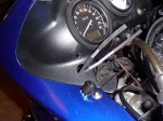 Run the element wires through the hole from the back of the dash along with a power and a ground wire that will be run to the distribution block. I just left the power and ground wire on the spools at this point (although not shown in this picture).
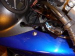 Wire up the switch as per the directions provided by Symtec. Carefully solder the wires to the switch and plan ahead to make sure that you slide the shrink tubing onto the wires (and far enough that the heat from the soldering doesn’t shrink the tubing too soon!) before you start to solder. Don’t ask me why I know that this is important.
- Once the wires are soldered to the switch, run the power and ground back to the distribution block. Find a routing that is protected and out of sight. I actually used a length of electrical tape to keep the power and ground together and to make them less visible and maybe even add a little abrasion protection. I followed the main wiring harness most of the way back towards the battery. Zip tie everything down securely.
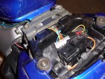 Hook up the power and ground to the distribution block. This picture shows the distribution block wired up to power the heated grips as well as some accessory lighting on Brenda’s motorbike.
- Test the grips. On high, they should warm up noticeably quite quickly.
- If everything is OK, snap the switch into it’s hole and check that the wires in behind are not binding on anything, an extra zip tie or two might be needed.
- Check one last time for free movement of the throttle and the handle bars.
- If everything is good, then you can start to anticipate warm hands on your next early morning ride as you replace the seats and put the tools away.
Leave a Reply
You must be logged in to post a comment.